The 2001 IRC with 2002 Proposals
4/17/00
SECTION R1001
MASONRY FIREPLACES
R1001.1 Definition. A masonry fireplace is a fireplace constructed of concrete or masonry. Masonry fireplaces shall be constructed in accordance with this section.
R1001.2 Footings and foundations. Footings for masonry fireplaces and their chimneys shall be constructed of concrete or solid masonry at least 12 inches (305 mm) thick and shall extend at least 6 inches (153 mm) beyond the face of the fireplace or foundation wall on all sides. Footings shall be founded on natural undisturbed earth or engineered fill below frost depth. In areas not subjected to freezing, footings shall be at least 12 inches (305 mm) below finished grade.
R1001.2.1 Ash dump cleanout. Cleanout openings located within foundation walls below fireboxes, when provided, shall be equipped with ferrous metal or masonry doors and frames constructed to remain tightly closed, except when in use. Cleanouts shall be accessible and located so that ash removal will not create a hazard to combustible materials.
R1001.3 Seismic reinforcing. Masonry or concrete fireplaces shall be constructed, anchored, supported and reinforced as required in this chapter. In Seismic Design Category D, masonry and concrete fireplaces shall be reinforced and anchored as detailed in Section R1001.3.1, R1001.3.2, R1001.4 and R1001.4.1. In Seismic Design Categories A, B or C, reinforcement and seismic anchorage is not required. In Seismic Design Categories E and F, masonry and concrete fireplaces shall be reinforced in accordance with the requirements of Section 2101 through 2109.
R1001.3.1 Vertical reinforcing. For fireplaces up to 40 inches (1016 mm) wide, four No. 4 continuous vertical bars, anchored in the foundation, shall be placed in the concrete, or between wythes of solid masonry, or within the cells of hollow unit masonry, and grouted in accordance with Section 2103.10. For fireplaces greater than 40 inches (1016 mm) wide, two additional No. 4 vertical bars shall be provided for each additional 40 inches (1016 mm) in width or fraction thereof.
R1001.3.2 Horizontal reinforcing. Vertical reinforcement shall be placed
enclosed within 1/4-inch ties, or other reinforcing of equivalent net
cross-sectional area, spaced not to exceed 18-inches on center in concrete,
or placed in the bed joints of unit masonry, at a minimum of every 18 inches (457 mm) of vertical height. Two such ties shall be provided at each bend in the vertical bars.
R1001.4 Seismic anchorage. Masonry and concrete fireplaces in Seismic Design Category D shall be anchored at each floor, ceiling or roof line more than 6 feet (1829 mm) above grade, except where constructed completely within the exterior walls. Anchorage shall conform to the following requirements:
R1001.4.1 Anchorage. Two 3/16-inch by 1-inch (4.8 mm by 25 mm) straps shall be embedded a minimum of 12 inches (305 mm) into the chimney. Straps shall be hooked around the outer bars and extend 6 inches (153 mm) beyond the bend. Each strap shall be fastened to a minimum of four floor joists with two 1/2-inch (12.7 mm) bolts.
R1001.5 Firebox walls. Masonry fireboxes shall be constructed of solid masonry units, hollow masonry units grouted solid, stone, or concrete. When a lining of firebrick at least 2 inches (51 mm) in thickness or other approved lining is provided, the minimum thickness of back and side walls shall each be 8 inches (203 mm) of solid masonry, including the lining. The width of joints between firebricks shall not be greater than 1/4 inch (6.4 mm). When no lining is provided, the total minimum thickness of back and side walls shall be 10 inches (254 mm) of solid masonry. Firebrick shall conform to ASTM C 27 or C 1261 and shall be laid with medium-duty refractory mortar conforming to ASTM C 199.
R1001.5.1 Steel fireplace units. Steel fireplace units may be installed with solid masonry to form a masonry fireplace when installed either according to the requirements of their listing or according to the requirements of this section.
Steel fireplace units incorporating a firebox lining shall be constructed with steel not less than 1/4 inch (6.4 mm) in thickness and an air circulating chamber which is ducted to the interior of the building. The firebox lining shall be encased with solid maosnry to provide a total thickness at the back and sides of not less than 8 inches (203 mm), of which not less than 4 inches (102 mm) shall be of solid masonry or concrete. Circulating air ducts employed with steel fireplace units shall be constructed of metal or masonry.
R1001.6 Firebox dimensions. The firebox of a concrete or masonry fireplace shall have a minimum depth of 20 inches (508 mm). The throat shall not be less than 8 inches (203 mm) above the fireplace opening. The throat opening shall not be less than 4 inches (102 mm) in depth. The cross-sectional area of the passageway above the firebox, including the throat, damper and smoke chamber, shall not be less than the cross-sectional area of the flue.
Exception: Rumford fireplaces shall be permitted provided that the depth of the fireplace be at least 12 inches (305 mm) and at least one-third of the width of the fireplace opening, and that the throat be at least 12 inches (305 mm) above the lintel, and be at least 1/20 the cross-sectional area of the fireplace opening.
R1001.7 Lintel and throat. Masonry over a fireplace opening shall be supported by a lintel of non-combustible material. The minimum required bearing length on each end of the fireplace opening shall be 4 inches (102 mm). The fireplace throat or damper shall be located a minimum of 8 inches (203 mm) above the top of the fireplace opening.
Reason: Redundant of R1001.6
R1001.7.1 Damper. Masonry fireplaces shall be equipped with a ferrous metal damper located at least 8 inches (203 mm) above the top of the fireplace opening. Dampers shall be installed in the fireplace or the chimney venting the fireplace, and shall be operable from the room containing the fireplace and accessable for maintenance.
Reason: A damper other than at the throat or the chimney top could be blocking and difficult to access.
R1001.8 Smoke chamber. Smoke chamber walls shall be constructed of solid masonry units, stone or concrete. Corbeling of masonry units shall not leave unit cores exposed to the inside of the smoke chamber. When a lining of firebrick at least 2 inches (51 mm) thick, or a lining of vitrified clay at least 5/8 inch (16 mm) thick, is provided, the total minimum thickness of front, back and side walls shall be 6 inches (153 mm) of solid masonry, including the lining. Firebrick shall conform to ASTM C 27 or C 1261 and shall be laid with refractory mortar conforming to ASTM C 199. Where no lining is provided, the total minimum thickness of front, back and side walls shall be 8 inches (203 mm) of solid masonry. When the inside surface of the smoke chamber is formed by corbeled masonry the inside surface shall be parged smooth.
R1001.8.1 Smoke chamber dimensions. The inside height of the smoke chamber, from the fireplace throat to the beginning of the flue, shall not be greater than the inside width of the fireplace opening. The inside surface of the smoke chamber shall not be inclined more than 45 degrees from vertical when prefabricated smoke chamber linings are used, or when the smoke chamber walls are rolled or sloped rather than corbeled. When the inside surface of the smoke chamber is formed by corbeled masonry, the walls shall not be corbeled more than 30 degrees from vertical.
[Combine R1001.9 through R1001.10 and make hearth extension 4" thick.]
R1001.9 Hearth and hearth extension. Masonry fireplace hearths and hearth extensions shall be constructed of concrete or masonry, supported by non-combustible materials and reinforced to carry their own weight and all imposed loads. No combustible material shall remain against the underside of hearths and hearth extensions after construction.
R1001.9.1 Hearth thickness. The minimum thickness of fireplace hearths shall be 4 inches (102 mm).
R1001.9.2 Hearth extension thickness. The minimum thickness of hearth extensions shall be 2 inches (51 mm).
Exception: When the bottom of the firebox opening is raised at least 8 inches (203 mm) above the top of the hearth extension, a hearth extension of not less than 3/8-inch-thick (9.5 mm) brick, concrete, stone, tile or other approved non-combustible material is permitted if it is sealed to the fireplace with a metal safety strip, and underlaid with either minimum 1/8 inch (3 mm) steel, 7/16 inch (10 mm) cement board or equivalent thickness of non-combustible underlayment. Combustible materials may remain beneath hearth extensions after construction if they meet the criteria of this exception.
R1001.10 Hearth extension dimensions. Hearth extensions shall extend at least 16 inches (406 mm) in front of, and at least 8 inches (203 mm) beyond, each side of the fireplace opening. Where the fireplace opening is 6 square feet (0.557 m2) or larger, the hearth extension shall extend at least 20 inches (508 mm) in front of, and at least 12 inches (305 mm) beyond, each side of the fireplace opening.
R1001.11 Fireplace clearance. All wood beams, joists, studs, and other combustible material shall have a clearance of not less than 2 inches (51 mm) from the front faces and sides of masonry fireplaces and not less than 4 inches (102 mm) from the back faces of masonry fireplaces. The air space shall not be filled, except to provide fire blocking in accordance with Section R1003.12.
Exceptions:
1. Masonry fireplaces listed and labeled for use in contact with combustibles in accordance with UL 127, and installed in accordance with the manufacturer's installation instructions, are permitted to have combustible material in contact with their exterior surfaces.
2. When masonry fireplaces are constructed as part of masonry or concrete walls, combustible materials shall not be in contact with the masonry or concrete walls less than 12 inches (306 mm) from the inside surface of the nearest firebox lining.
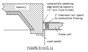
3. Exposed combustible trim and the edges of sheathing materials, such as wood siding, flooring and drywall, shall be permitted to abut the masonry fireplace side walls and hearth extension, in accordance with FIGURE R1003.12, provided such combustible trim or sheathing is a minimum of 12 inches (306 mm) from the inside surface of the nearest firebox lining.
4. Exposed combustible mantels or trim may be placed directly on the masonry fireplace front surrounding the fireplace opening provided such combustible materials shall not be placed within 6 inches (153 mm) of a fireplace opening. Combustible material within 12 inches (305 mm) of the fireplace opening shall not project more than 1/8 inch (3.2 mm) for each 1-inch (25 mm) distance from such opening.
R1001.11 Fireplace clearance. Combustible material shall have a clearance of not less than 2 inches (51 mm) from the front faces and sides of masonry fireplaces and not less than 4 inches (102 mm) from the back faces of masonry fireplaces. The air space shall not be filled, except to provide fire blocking in accordance with Section R1003.12.
Exceptions:
1. Masonry fireplaces listed and labeled for use in contact with combustibles in accordance with UL 127, and installed in accordance with the manufacturer's installation instructions, are permitted to have combustible material in contact with their exterior surfaces.
2. Combustible materials, including framing, wood siding, flooring and trim, shall be permitted to abut the sides and hearth extentions, but not the backs, of masonry fireplaces, in accordance with FIGURE R1003.12, provided such combustible materials are a minimum of 12 inches (306 mm) from the inside surface of the nearest firebox lining.
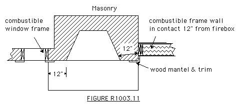
4. Exposed combustible mantels or trim may be placed directly on the masonry fireplace front surrounding the fireplace opening provided such combustible materials shall not be placed within 6 inches (153 mm) of a fireplace opening. Combustible material within 12 inches (305 mm) of the fireplace opening shall not project more than 1/8 inch (3.2 mm) for each 1-inch (25 mm) distance from such opening.
Reason: Simplify and clarify code based on safety testing results
R1001.12 Fireplace fire blocking. All spaces between fireplaces and floors and ceilings through which fireplaces pass shall be fire blocked with non-combustible material securely fastened in place. The fire blocking of spaces between wood joists, beams or headers shall be to a depth of 1 inch (25mm) and shall only be placed on strips of metal or metal lath laid across the spaces between combustible material and the chimney.
TABLE R1001.1
SUMMARY OF REQUIREMENTS FOR MASONRY FIREPLACES AND CHIMNEYS
NOTE:
This table provides a summary of major requirements for the construction of masonry chimneys and fireplaces. Letter references are to Figure R1001.1, which shows examples of typical construction. This table does not cover all requirements, nor does it cover all aspects of the indicated requirements. For the actual mandatory requirements of the code, see the indicated section of text.
| ITEM | LETTER | REQUIREMENTS | SECTION |
| Hearth and hearth extension thickness | A | 4-inch minimum thickness for hearth.
4-inch minimum thickness for hearth extension | R1001.9 |
| Hearth extension (each side of opening) | B | 8 inches for fireplace opening less than 6 square feet. 12 inches for fireplace opening greater than
or equal to 6 square feet. | R1001.10 |
| Hearth extension (front of opening) | C | 16 inches for fireplace opening less than 6 square feet. 20 inches for fireplace opening greater than
or equal to 6 square feet. | R1001.10 |
| Firebox dimensions | D | 20-inch minimum firebox depth. 12-inch minimum firebox depth for Rumford fireplaces. | R1001.11 |
| Hearth and hearth extension reinforcing | E | Reinforced to carry its own weight and all
imposed loads | R1001.9 |
| Thickness of wall of firebox | F | 10 inches solid masonry or 8 inches where firebrick lining is used. | R1001.5 |
| Distance from top of opening to throat | G | 8 inches minimum. | R1001.7 |
| Smoke chamber Wall thickness Dimensions | H | 6 inches lined; 8 inches unlined. Not taller than opening width; walls not inclined more than 45 degrees from vertical for prefabricated smoke chamber linings or 30 degrees from vertical for corbeled masonry. | R1001.8 |
| Chimney vertical reinforcing | I | Four No. 4 full-length bars for chimney up to 40 inches wide. Add two No. 4 bars for each additional 40 inches or fraction of width, or for each additional flue. | R1001.3.1 |
| Chimney horizontal reinforcing | J | 1/4-inch ties at each 18 inches, and two ties at each bend in vertical steel. | R1001.3.2 |
| Fireplace lintel | K | Non-combustible material with 4-inch bearing length of each side of opening. | R1001.7 |
| Chimney walls with flue lining | L | 4-inch-thick solid masonry with 5/8-inch fireclay liner or equivalent. 1/2-inch grout or airspace between fireclay liner and wall. | R1001.6
R1001.7 |
| Effective flue area (based on area of fireplace opening and chimney) | M | See Section 2113.12 | R1003.12 |
Clearances
From chimney
From fireplace
Combustible trim or materials
Above roof | N | 2 inches interior, 1 inch exterior or 12" from lining.
2 inches back or sides or 12" from lining.
6 inches from opening.
3 feet above roof penetration, 2 feet above part of structure within 10 feet. | R1001.14
R1001.11
R1001.12
R1001.5 |
Anchorage
Strap
Number
Embedment into chimneyFasten to
Bolts | O | 3/16 inch by 1 inch.
Two
12 inches hooked around outer bar with 6-inch extension.
4 joists.feet.
Two 1/2-inch diameter. | R1001.4 |
Footing
Thickness
Width | P | 12-inch minimum.
6 inches each side of fireplace wall. | R1001.2 |
For SI: 1 inch = 25.4 mm, 1 foot = 304.8 mm, 1 square foot = 0.0929 m2.

SECTION R1002
FACTORY-BUILT FIREPLACES
R1002.1 General. Factory-built fireplaces shall be listed and labeled and shall be installed in accordance with the conditions of the listing. Factory-built fireplaces shall be tested in accordance with UL 127.
R1002.2 Hearth extensions: Hearth extensions of approved factory-built fireplaces and fireplace stoves shall be installed in accordance with the listing of the fireplace. The hearth extension shall be readily distinguishable from the surrounding floor area.
R1002.3 Decorative Shrouds. Decorative shrouds shall not be installed at the termination of chimneys for factory-built fireplaces except where such shrouds are listed and labeled for use with the specific factory-built fireplace system and installed in accordance with the manufacturer's installation instructions.
R1002.4 Unvented gas log heaters. An unvented gas log heater shall not be installed in a factory built fireplace unless the fireplace has been specifically tested, listed and labeled for such use in accordance with UL 127.
SECTION R1003
FACTORY-BUILT FIREPLACE STOVES
R1003.1 General. Factory-built fireplace stoves, consisting of a freestanding fire chamber assembly, that have been tested and are listed by a nationally recognized testing laboratory, shall be installed in accordance with the requirements of said listing and the manufacturer's instructions. The supporting structure for a hearth extension shall be at the same level as the supporting structure for the fireplace unit.
SECTION R1004
EXTERIOR AIR
R1004.1 Exterior air. Factory-built or masonry fireplaces covered in this chapter shall be equipped with an exterior air supply to assure proper fuel combustion unless the room is mechanically ventilated and controlled so that the indoor pressure is neutral or positive. When installed, combustion air supplies for fireplaces shall be installed in accordance with this section.
R1004.1.1 Factory-built fireplaces. Exterior combustion air ducts for factory-built fireplaces shall be a listed component of the fireplace and shall be installed according to the fireplace manufacturer�s instructions.
R1004.1.2 Masonry fireplaces. Listed combustion air ducts for masonry fireplace shall be installed according to the terms of their listing and manufacturer�s instructions.
R1004.2 Exterior air intake. The exterior air intake shall be capable of providing all combustion located to supply air from the exterior of the dwelling or from spaces within the dwelling ventilated with outside air such as crawl or attic spaces. The exterior air intake shall not be located within the garage or basement of the dwelling nor shall the air intake be located at an elevation higher than the firebox. The exterior air intake shall be covered with a corrosion-resistant screen of 1/4 inch (6.4 mm) mesh.
R1004.3 Clearance. Unlisted combustion air ducts shall be installed with a minimum 1-inch (25 mm) clearance to combustibles for all parts of the duct within 5 feet (1524 mm) of the duct outlet.
R1004.4 Passageway. The combustion air passageway shall be a minimum of 6 square inches (3870 mm2) and not more than 55 square inches (0.035 m2) except that combustion air systems for listed fireplaces shall be constructed according to the fireplace manufacturer�s instructions.
R1004.5 Outlet. The exterior air outlet is permitted to be located in the back or sides of the firebox chamber, or within 24 inches (610 mm) of the firebox opening on or near the floor. shall terminate outside the fireplace combustion chamber and not within 6 inches of the fireplace opening. The outlet shall be closable and designed to prevent burning material from dropping into concealed combustible spaces.
R1004.1 Combustion air. Factory-built or masonry fireplaces covered in this chapter which have a net opening exceeding 6 square feet (0.557 m2) shall be provided with combustion air supply to assure proper fuel combustion and exhaust of flue gasses by:
(a) providing to the room containing the fireplace at least one cubic foot per minute (cfm) of make up air for each square inch of flue size as determined by TABLE 2116.12b, or
(b) providing a supply of combustion air from the exterior of the dwelling directly to the fireplace in accordance with 2116.2
R1004.2 Direct exterior combustion air. Where a supply of combustion air is provided from the exterior of the dwelling directly to the appliance, the following requirements shall be met:
R1004.2.1 Factory-built fireplaces. Exterior combustion air ducts for factory-built fireplaces shall be listed as a component of the fireplace and shall be installed according to the fireplace manufacturer's instructions.
R1004.2.2 Masonry fireplaces. Exterior combustion air ducts for masonry fireplaces shall be a minimum of 6 square inches (3870 mm2) and not more than 55 square inches (0.035 m2) except that combustion air systems for listed or certified fireplaces shall be constructed according to the fireplace manufacturer's instructions.
R1004.2.3 Exterior air intake. The exterior air intake shall be located on the exterior of the dwelling or from spaces within the dwelling ventilated with outside air such as crawl or attic spaces. The exterior air intake shall not be located within the garage, or basement of the dwelling. The air intake shall not be located at an elevation higher than the firebox. The exterior air intake shall be covered with a corrosion-resistant screen of 1/4-inch (6.4 mm) mesh.
R1004.2.4 Clearance. Unlisted combustion air ducts shall be installed with a minimum 1-inch (25 mm) clearance to combustibles for all parts of the duct within 5 feet (1524 mm) of the duct outlet at the appliance. Where any part of the exterior air system is not entirely within the masonry walls of the fireplace or the fireplace foundation, the system shall be fitted with a back draft damper to prevent back drafting.
R1004.2.5 Outlet. The exterior air outlet is permitted to be located in the hearth, back or sides of the firebox chamber, or within 24 inches (610 mm) of the firebox opening on or near the floor. The outlet shall be closable and designed to prevent burning material from dropping into concealed combustible spaces.
Reason: This proposal takes a fresh look at the issue of requiring an exterior source of combustion air for fireplaces. The proposed language would allow for flexibility in insuring that fireplaces are provided with adequate combustion air and are capable of exhausting flue gasses. It provides guidelines about the capacity of combustion air needed based on established ASHRAE provisions and the existing flue sizing table in the IBC code.* The proposal also prescribes ways to prevent backdrafting and improve fire safety.
* The 1979 ASHRAE Handbook reports on empirical studies which show that modern masonry fireplaces require a minimum average face velocity or 0.2 feet/second in order to exhaust all the products of combustion. According to this calculation, a fireplace with an opening of 6 square feet would need a minimum of only 72 cfm so we exempted fireplaces smaller than 6 square feet in opening area. This same fireplace, with a 12"x12" flue at one cfm per square inch of cross-sectional flue area would, from TABLE 2116.12b require 91 cfm and a four foot wide fireplace with a 16"x20" flue would require a minimum of 214 cfm makeup air. While these fireplaces might actually require more air with a brisk fire, the greatest potential for spillage is when the fire is dying down and the draft and required makeup air volumes are reduced, so we think sizing the minimum makeup air requirement to the flue size and based on the ASHRAE formula is about right and easy to regulate without having to go beyond the IBC code.
SECTION R1005
MASONRY HEATERS
R1005.1 Installation. A Masonry Heater shall be installed according to one of the following:
1. the terms of its listing, or
2. ASTM E-1602
R1005.2 Seismic reinforcing. Masonry heaters shall be anchored and reinforced as required in this chapter. All masonry heaters shall maintain a minimum clearance of 4 inches (102 mm) to adjacent framing from the body of the masonry heater. In Seismic Design Categories A, B and C reinforcement and seismic anchorage shall not be required. In Seismic Design Categories D1 and D2 masonry heaters shall be anchored to the foundation. Where the masonry chimney shares a common wall with the facing of the masonry heater, the chimney portion of the structure shall be reinforced in accordance with Section R1003.3.
SECTION R1006
MASONRY CHIMNEYS
R1006.1 Definition. A masonry chimney is a chimney constructed of concrete or
masonry. Masonry chimneys shall be constructed, anchored, supported and reinforced as required in this chapter.
R1006.2 Footings and foundations. Footings for masonry chimneys shall be constructed of concrete or solid masonry at least 12 inches (305 mm) thick and shall extend at least 6 inches (153 mm) beyond the face of the foundation or support wall on all sides. Footings shall be founded on natural undisturbed earth or engineered fill below frost depth. In areas not subjected to freezing, footings shall be at least 12 inches (305 mm) below finished grade.
R1006.3 Seismic reinforcing. Masonry or concrete chimneys shall be constructed, anchored, supported and reinforced as required in this chapter. In Seismic Design Category D-1 and D-2, masonry and concrete chimneys shall be reinforced and anchored as detailed in Section R1006.3.1 and R1006.3.2. In Seismic Design Categories A, B or C, reinforcement and seismic anchorage is not required. In Seismic Design Categories E and F, masorny and concrete chimneys shall be reinforced in accordance with the requirements of Section 2101 through 2109.
R1006.3.1 Vertical reinforcing. For chimneys up to 40 inches (1016 mm) wide, four No. 4 continuous vertical bars, anchored in the foundation, shall be placed in the concrete, or between wythes of solid masonry, or within the cells of hollow unit masonry, and grouted in accordance with Section R609. Grout shall be prevented from bonding with the flue liner so that the flue liner is free to move with thermal expansion. For chimneys greater than 40 inches (1016 mm) wide, two additional No. 4 vertical bars shall be provided for each additional 40 inches (1016 mm) in width or fraction thereof.
R1006.3.2 Horizontal reinforcing. Vertical reinforcement shall be placed
enclosed within 1/4-inch ties, or other reinforcing of equivalent net
cross-sectional area, spaced not to exceed 18-inches on center in concrete,
or placed in the bed joints of unit masonry, at a minimum of every 18 inches (457 mm) of vertical height. Two such ties shall be provided at each bend in the vertical bars.
R1006.4 Seismic anchorage. Masonry and concrete chimneys and foundations in Seismic Design Category D shall be anchored at each floor, ceiling or roof line more than 6 feet (1829 mm) above grade, except where constructed completely within the exterior walls. Anchorage shall conform to the following requirements:
R1006.4.1 Anchorage. Two 3/16-inch by 1-inch (4.8 mm by 25 mm) straps shall be embedded a minimum of 12 inches (305 mm) into the chimney. Straps shall be hooked around the outer bars and extend 6 inches (153 mm) beyond the bend. Each strap shall be fastened to a minimum of four floor joists with two 1/2-inch (12.7 mm) bolts.
R1006.5 Corbeling. Masonry chimneys shall not be corbeled more than half of the chimney's wall thickness from a wall or foundation, nor shall a chimney be corbeled from a wall or foundation which is less than 12 inches (305 mm) in thickness unless it projects equally on each side of the wall, except that on the second story of a two-story dwelling, Corbeling of chimneys on the exterior of the enclosing walls may equal the wall thickness. The projection of a single course shall not exceed one-half the unit height or one-third of the unit bed depth, whichever is less.
R1006.6 Changes in dimension. The chimney wall or chimney flue lining shall not change in size or shape within 6 inches (153 mm) above or below where the chimney passes through floor components, ceiling components or roof components.
R1006.7 Offsets. Where a masonry chimney is constructed with a fireclay flue liner surrounded by one wythe of masonry, the maximum offset shall be such that the centerline of the flue above the offset does not extend beyond the center of the chimney wall below the offset. Where the chimney offset is supported by masonry below the offset in an approved manner, the maximum offset limitations shall not apply. Each individual corbeled masonry course of the offset shall not exceed the projection limitations specified in Section R1006.5.
R1006.8 Additional load. Chimneys shall not support loads other than their own weight unless they are designed and constructed to support the additional load. Masonry chimneys shall be permitted to be constructed as part of the masonry walls or concrete walls of the building.
R1006.9 Termination. Chimneys shall extend at least 2 feet (610 mm) higher than any portion of the building within 10 feet (3048 mm), but shall not be less than 3 feet (914 mm) above the point where the chimney passes through the roof.
R1006.10 Wall thickness. Masonry chimney walls shall be constructed of
concrete, solid masonry units, or hollow masonry units grouted solid with
not less than 4 inches nominal thickness.
R1006.11 Flue lining (material). Masonry chimneys shall be lined. The lining material shall be appropriate for the type of appliance connected, according to the terms of the appliance listing and manufacturer's instructions.
R1006.11.1 Residential-type appliances (general). Flue lining systems shall comply with one of the following:
1. Clay flue lining complying with the requirements of ASTM C 315, Specifications for Clay Flue Linings, or equivalent.
2. Listed chimney lining systems complying with UL 1777, Chimney Liners.
3. Factory-built chimneys or chimney units listed for installation within masonry chimneys.
R1006.11.2 Flue Linings for Specific Appliances. Flue linings other than covered in Section R1006.11.1 intended for use with specific appliances, shall comply with Sections 2113.11.2.1 through 2113.11.1.4 and Sections 2113.11.2 and 2113.11.3
R1006.11.3 Gas Appliances Flue lining systems for gas appliances shall be in accordance with the International Fuel Gas Code.
R1006.11.4 Pellet fuel-burning appliances Flue lining and vent systems for use in masonry chimneys with pellet fuel-burning appliances shall be limited to the following:
1) Flue lining systems complying with Section R1006.11.1
2) Pellet vents listed for installation within masonry chimneys (see Section R1006.11.6 for marking.)
R1006.11.5 Oil fired appliances approved for use with L-vent Flue lining and vent systems for use in masonry chimneys with oil fired appliances approved for use with Type L vent shall be limited to the following:
1) Flue lining systems complying with Section R1006.11.1
2) Listed chimney liners complying with UL 641. (see Section 2113.11.1.5 for marking.)
R1006.11.6 Notice of usage When a flue is relined with a material not complying with Section R1006.11.1 the chimney shall be plainly and permanently identified by a label attached to a wall ceiling or other conspicuous location adjacent to where the connector enters the chimney. the label shall include the following message or equivalent language. "This chimney is for use only with [Type or category] of appliance that burn [type of fuel]. Do not connect other types of appliances."
R1006.12 Flue lining (installation). Flue liners shall be installed in accordance with ASTM C 1283 and extend from a point not less than 8 inches (203 mm) below the lowest inlet or, in the case of fireplaces, from the top of the smoke chamber, to a point above the enclosing walls. The lining shall be carried up vertically, with a maximum slope no greater than 30 degrees from the vertical.
Fireclay flue liners shall be laid in medium-duty refractory mortar conforming to ASTM C 199 with tight mortar joints left smooth on the inside and installed to maintain an air space or insulation not to exceed the thickness of the flue liner separating the flue liners from the interior face of the chimney masonry walls. Flue lining shall be supported on all sides. Only enough mortar shall be placed to make the joint and hold the liners in position.
R1006.12.1 Listed materials. Listed materials used as flue linings shall be installed in accordance with the terms of their listings and manufacturer's instructions.
R1006.12.2 Space around lining. The space surrounding a chimney lining system or vent installed within a masonry chimney shall not be used to vent any other appliance.
Exception: This shall not prevent the installation of a separate flue lining in accordance with the manufacturers installation instructions.
R1006.13 Multiple flues. When two or more flues are located in the same chimney, masonry wythes shall be built between adjacent flue linings. The masonry wythes shall be at least 4 inches (102 mm) thick and bonded into the walls of the chimney.
Exception: When venting only one appliance, two flues may adjoin each other in the same chimney with only the flue lining separation between them. The joints of the adjacent flue linings shall be staggered at least 4 inches (178 mm).
R1006.14 Flue area (appliance). Chimney flues shall not be smaller in area than that of the area of the connector from the appliance. The sizing of a chimney flue to which multiple-appliance venting systems are connected shall be in accordance with Section M1805.3.
R1006.15 Flue area (masonry fireplace). Flue sizing for chimneys serving fireplaces shall be in accordance with Sections R1006.15.1 or R1006.15.2
R1006.15.1 Round chimney flues shall have a minimum net cross-sectional area of at least 1/12 of the fireplace opening. Square chimney flues shall have a minimum net cross-sectional area of at least 1/10 of the fireplace opening. Rectangular chimney flues with an aspect ratio less than 2 to 1 shall have a minimum net cross-sectional area of at least 1/10 of the fireplace opening. Rectangular chimney flues with an aspect ratio of 2 to 1 or more shall have a minimum net cross-sectional area of at least 1/8 of the fireplace opening.
R1006.15.2 The minimum net cross-sectional area of the flue shall be determined in accordance with Figure R1006.15. A flue size providing at least the equivalent net cross-sectional area shall be used. Cross-sectional areas of clay flue linings are provided in Tables R1006.15a and R1006.15b or as provided by the manufacturer or as measured in the field. The height of the chimney shall be measured from the firebox floor to the top of the chimney flue.
FIGURE R1006.15
FLUE SIZES FOR MASONRY CHIMNEYS
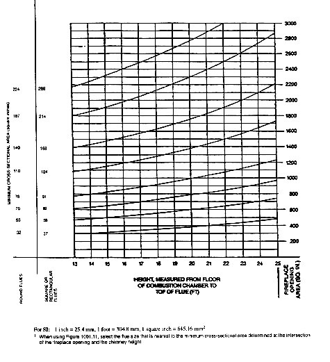
TABLE R1006.15a
NET CROSS-SECTIONAL AREA
OF ROUND FLUE SIZES (1)
FLUE SIZE, INSIDE DIAMETER
(inches) | CROSS-SECTIONAL AREA
(square inches) |
| 6 | 28 |
| 7 | 38 |
| 8 | 50 |
| 10 | 78 |
| 10-3/4 | 90 |
| 12 | 113 |
| 15 | 176 |
| 18 | 254 |
For SI: 1 inch = 25.4 mm, 1 square inch = 645.16 mm2.
1 Flue sizes are based on ASTM C 315-91.
TABLE R1006.15b
NET CROSS-SECTIONAL AREA
OF SQUARE AND RECTANGULAR FLUE SIZES (1)
FLUE SIZE, OUTSIDE DIMENSIONS
(inches) | CROSS-SECTIONAL AREA
(square inches) |
| 4-1/2 x 13 | 34 |
| 7-1/2 x 7-1/2 | 37 |
| 8-1/2 x 8-1/2 | 47 |
| 7-1/2 x 11-1/2 | 58 |
| 8-1/2 x 13 | 74 |
| 7-1/2 x 15-1/2 | 82 |
| 11-1/2 x 11-1/2 | 91 |
| 8-1/2 x 17-1/2 | 101 |
| 13 x 13 | 122 |
| 11-1/2 x 15-1/2 | 124 |
| 13 x 17-1/2 | 165 |
| 15-1/2 x 15-1/2 | 168 |
| 15-1/2 x 19-1/2 | 214 |
| 17-1/2 x 17-1/2 | 226 |
| 19-1/2 x 19-1/2 | 269 |
| 20 x 20 | 286 |
For SI: 1 inch = 25.4 mm, 1 square inch = 645.16 mm2.
1 Flue sizes are based on ASTM C 315.
R1006.16 Inlet. Inlets to masonry chimneys shall enter from the side. Inlets shall have a thimble of fireclay, rigid refractory material or metal that will prevent the connector from pulling out of the inlet or from extending beyond the wall of the liner.
R1006.17 Masonry chimney cleanout openings. Cleanout openings shall be provided within 6 inches (153 mm) of the base of each flue within every masonry chimney. The upper edge of the cleanout shall be located at least 6 inches (153 mm) below the lowest chimney inlet opening. The height of the opening shall be at least 6 inches (153 mm). The cleanout shall be provided with a non-combustible cover.
Exceptions: Chimney flues serving masonry fireplaces, where cleaning is possible through the fireplace opening.
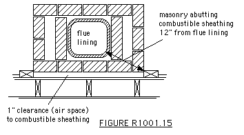
R1006.18 Chimney clearances. Any portion of a masonry chimney located in the interior of the building or within the exterior wall of the building shall have a minimum air space clearance to combustibles of 2 inches (51 mm). Chimneys located entirely outside the exterior walls of the building, including chimneys that pass through the soffit or cornice, shall have a minimum air space clearance of 1 inch (25 mm). The air space shall not be filled, except to provide fire blocking in accordance with Section R602.8.
R1006.18.1 Chimneys with UL Listed Lining Systems. Masonry chimneys equipped with a chimney lining system listed and labeled for use in chimneys in contact with combustibles in accordance with UL 1777, and installed in accordance with the manufacturer's installation instructions, are permitted to have combustible material in contact with their exterior surfaces. However, this shall not eliminate the requirement for noncombustible fire blocking in accordance with Section R1001.19.
R1006.18.2 Combustible Trim and Weatherstopping. Chimneys located entirely outside the exterior walls of the building shall be permitted to abut the combustible exterior wall of the building provided combustible material in contanct with the chimney is a minimum of 12 inches (306 mm) from the inside surface of the nearest flue lining.
R1006.18.3 masonry walls.
When masonry chimneys are constructed as part of masonry or concrete walls, combustible materials shall not be in contact with the masonry or concrete wall less than 12 inches (306 mm) from the inside surface of the nearest flue lining.
Exceptions:
1. Masonry chimneys equipped with a chimney lining system listed and labeled for use in chimneys in contact with combustibles in accordance with UL 1777, and installed in accordance with the manufacturer's installation instructions, are permitted to have combustible material in contact with their exterior surfaces. However, this shall not eliminate the requirement for noncombustible fire blocking in accordance with Section R1001.19.
2. Combustible material shall be permitted to abut the masonry chimney sidewalls, provided such combustible material is a minimum of 12 in. (305 mm) from the inside surface of the flue liner.
Reason: Reorganize section as a rule with exceptions. Create a general rule about combustibles rather than two similar rules for chimneys in contact with frame and masonry walls. The proposal is supported by recent testing at OMNI and comparison with "known-to-be-safe" conditions.
R1006.19 Chimney fire blocking. All spaces between chimneys and floors and ceilings through which chimneys pass shall be fire blocked with non-combustible material securely fastened in place. The fire blocking of spaces between wood joists, beams or headers shall be to a depth of 1 inch (25mm) and shall only be placed on strips of metal or metal lath laid across the spaces between combustible material and the chimney.
Exception: Chimneys built in accordance with Sections R1006.18.1, R1006.18.2, or R1006.18.3 may be fire blocked with combustible material.
R1006.20 Chimney crickets. Chimneys shall be provided with crickets when the dimension parallel to the ridge line is greater than 30 inches (762 mm) and does not intersect the ridge line. The intersection of the cricket and the chimney shall be flashed and counter flashed in the same manner as normal roof-chimney intersections. Crickets shall be constructed in conformity with Figure R1001.17 and Table R1001.17.
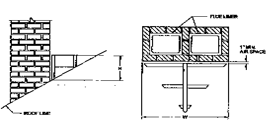
FIGURE R1006.21
CHIMNEY CRICKET
TABLE R1006.21
CRICKET DIMENSIONS
| ROOF SLOPE | H |
| 12 - 12 | 1/2 of W |
| 8 - 12 | 1/3 of W |
| 6 - 12 | 1/4 of W |
| 4 - 12 | 1/6 of W |
| 3 - 12 | 1/8 of W |
R1006.21 Spark arresters. Where a spark arrester is installed on a masonry chimney the spark arrestor shall meet all of the following requirements:
1. The net free area of the arrestor shall be not less than four (4) times the net free area of the outlet of the chimney flue it serves.
2. The arrestor screen shall have heat and corrosion resistance equivalent to nineteen (19) guage galvanized steel or twenty-four (24) guage stainless steel.
3. Openings shall not permit the passage of spheres having a diameter greater than one-half (1/2) inch (13 mm) nor block the passage of spheres having a diameter less than three-eight (3/8) inch (11 mm).
4. The spark arrestor shall be accessable for cleaning and the screen or chimney cap shall be removable to allow for cleaning of the flue.
SECTION R1007
FACTORY-BUILT CHIMNEYS
R1007.1 General. Factory-built chimneys shall be listed and labeled and shall be installed in accordance with the manufacturer's installation instructions.
R1007.2 Decorative Shrouds. Decorative shrouds shall not be installed at the termination of factory-built chimneys except where such shrouds are listed and labeled for use with the specific factory-built chimney system and installed in accordance with the manufacturer's installation instructions.
R1007.3 Solid fuel appliances. Factory-built chimneys for use with solid fuel-burning appliances shall comply with the Type HT requirements of UL 103.
Exception: Chimneys for use with fireplace stoves listed only to UL 737 shall comply with the requirements of UL 103.
R1007.4 Factory-built fireplaces. Chimneys for use with factory-built fireplaces shall comply with the requirements of UL 127.
R1007.5 Support. Where factory-built chimneys are supported by structural members, such as joists and rafters, such members shall be designed to suppord the additional load.
R1007.6 Medium-heat appliances. Factory-built chimneys for medium-heat appliances producing flue gasses having a temperature above 1,000 degrees F (538 degrees C), measured at the entrance to the chimney, shall comply with UL 959.

Back to Codes and Standards
[The Rumford Store]
[Rumford Picture Gallery]
[Specifications]
[Plans & Instructions]
[Manufacturers]
[Dealers]
[Architects]
[Builders]
[Masons]
[Sweeps]
[Associations]
[Masonry Chimneys]
[Masonry Heaters]
[Training]
[links]
[search]
[Superior Clay Corporation]

Buckley Rumford Fireplace Home Page
Copyright1996 - 1999 Jim Buckley
All rights reserved.