PLATES
EXPLANATION OF THE FIGURES
____________
|
PLATE VIII. FIG. 1.
The plan of a fireplace on the common construction. See page 349. FIG. 2. This figure shows the elevation, or front view, of a fireplace on the common construction. See page 349. |

|
|
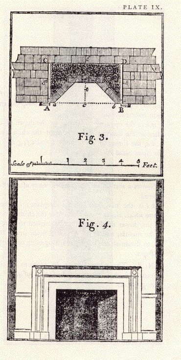
PLATE IX. FIG. 3. This figure shows how the fireplace represented by the Fig. I is to be altered, in order to its being improved. A B is the opening in front, C D the back, and A C and B D the covings of the fireplace in its original state. a b its opening in front, i k its back, and a i and b k its covings after it has been altered; e is a point upon the hearth upon which a plumb suspended from the middle of the upper part of the breast of the chimney falls. The situation for the new back is ascertained by taking the line e f equal to four inches. The new back and covings are represented as being built of bricks, and the space between these and the old back and covings as being filled up with rubbish. See page 350. FIG. 4. This figure represents the elevation or front view of the fireplace (Fig. 3) after it has been altered. The lower part of the doorway left for the chimney-sweeper is shown in this figure by white dotted lines. See page 352.
|
|
|
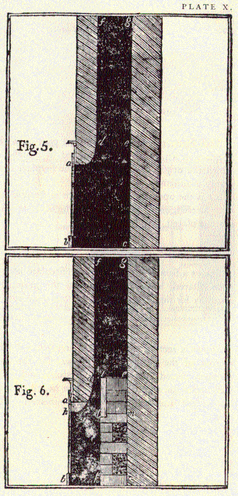
PLATE X. FIG. 5. This figure shows the section of a chimney fireplace and of a part of the canal of the chimney on the common construction. a b is the opening in front; b c the depth of the fireplace at the hearth; d the breast of the chimney. d e, the throat of the chimney, and d f, g e, a part of the open canal of the chimney. FIG. 6. Shows a section of the same chimney after it has been altered. k l is the new back of the fireplace; l i the tile or stone which closes the doorway for the chimney-sweeper; d i the throat of the chimney, narrowed to four inches; a, the mantle, and b, the new wall made under the mantle, to diminish the height of the opening of the fireplace in front. N. B. - These two figures are sections of the same chimney which is represented in each of the four preceding figures.
|
|
|
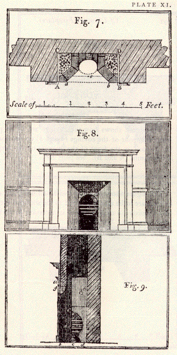
PLATE XI. FIG. 7. This figure represents the ground plan of a chimney fireplace in which the grate is placed in a niche, and in which the original width A B of the fireplace is considerably diminished. a b is the opening of the fireplace in front after it has been altered, and d is the back of the niche in which the grate is placed. See page 354. FIG. 8. Shows a front view of the same fireplace after it has been altered; where may be seen the grate, and the doorway for the chimney-sweeper. See page 354. FIG. 9. Shows a section of the same fireplace, c d e being a section of the niche, g the doorway for the chimney-sweeper, closed by a piece of firestone, and f the new wall under the mantle, by which the height of the opening of the fireplace in front is diminished. See page 354.
|
|
|
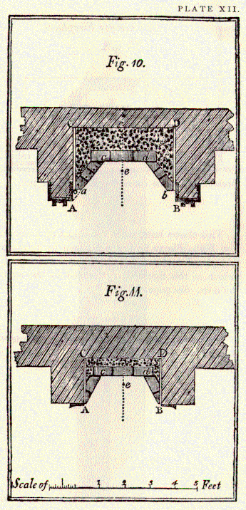
PLATE XII. FIG. 10. This figure shows how the covings are to be placed when the front of the covings (a and b) do not come so far forward as the front of the opening of the fireplace, or the jambs (A and B). See page 356. FIG. 11. This figure shows how the width and obliquity of the covings are to be accommodated to the width of the back of a fireplace, in cases where it is necessary to make the back very wide. See page 357.
|
|
|
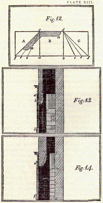
PLATE XIII. FIG. 12. This figure shows how an instrument called a bevel (m n), useful in laying out the work, in altering chimney fireplaces, may be constructed. See page 357. FIG. I 3. This shows how, when the breast of a chimney (d) is too high, it may be brought down by means of a wall (h) placed under the mantle, and a coating of plaster, which in this figure is represented by the part marked by dots. See page 359. FIG. 14. This shows how the breast of a chimney may be brought down merely by a coating of plaster. See page 359.
|
|
[Notes on the Website Publication]
[Advertisement]
[Chapter I]
[Chapter II]
[Chapter III]
[Plates]
[Supplementary Observations]
Buckley Rumford Fireplaces
Copyright 1996 - 2010 Jim Buckley
All rights reserved.
webmaster